This is an archive of information released in the past.
Disclaimer: It may contain broken links or outdated information. Some parts may not function in current web browsers.
*Visit https://humans-in-space.jaxa.jp/en/ for the latest information.

About Kibo
Pressurized Module
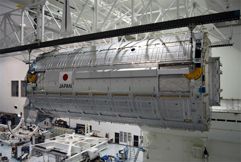
At NASA Kennedy Space Center, the PM before loading in the payload canister (Image credit: NASA)
Overview
The Pressurized Module (PM) is Kibo's main facility. All the system racks that are necessary for Kibo's on-orbit operations are installed in the PM.
The PM is the largest pressurized module on the International Space Station (ISS). Up to 23 racks (10 of which are International Standard Payload Racks (ISPRs)) can be accommodated in the PM.
The pressurized interior of the PM is maintained at one atmosphere (1atm), thus providing a shirt-sleeve working environment. Most crew activities related to Kibo, such as experiments, robotic operations, voice communications with the ground, and checkout or maintenance activities, are mainly performed in or from the PM.
The PM was delivered and installed on the ISS during STS-124 Mission (1J).
| Item | Specification | |
|---|---|---|
| Shape | Cylindrical | |
| Diameter | Outer | 4.4m |
| Inner | 4.2m | |
| Length | 11.2m | |
| Mass | 14.8t | |
| Number of Rack Places | Total racks: 23 * System Racks: 11 ISPR: 12 (10 for payload racks, 1 for freezer rack, and 1 for storage rack) |
|
| Power (provided from US segment) |
Max. 24kW 120V(Direct current) | |
| Environment | Temperature: 18.3~26.7℃ Humidity: 25~70% |
|
| Lifetime | More than 10 years | |
* Six racks can be installed in a row on each of the four walls inside the PM, except the zenith wall. The zenith wall can hold five racks in a row.
Structure
The PM body structure is designed to bear loads imposed during the space shuttle's launch, ascent, ISS attitude control and orbital maneuvers. The pressurized environment inside the PM is controlled by the Environment Control and Life Support System/Thermal Control System (ECLSS/TCS) and protected by the outer structure made of aluminum alloy. The PM's outer structure is covered by debris shield panels to protect the body from debris impacts. It has two windows on the port endcone. The hardware or tools aboard Kibo are mostly common for all of the ISS. However, some of the hardware or tools are Kibo-specific due to Kibo's unique design.
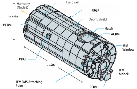
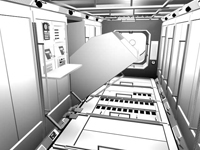
Structure of the PM
The PM is equipped with the following hardware;
JEM Airlock
The PM has an airlock through which Exposed Facility (EF) payloads or Orbital Replacement Units (ORUs) can be transferred between the PM and the EF. This airlock is not designed for egress/ingress of extravehicular activity (EVA) crew members. The JEM Airlock is Kibo-specific hardware.
JEM Windows
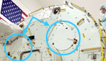
Two windows are located just the above the JEM Airlock.
Exposed Facility Berthing Mechanism (EFBM)
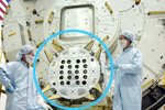
This is an attaching mechanism to connect the EF to the PM. The EFBM is mounted on the port endcone of the PM. This is Kibo-specific hardware.
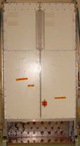
Common Berthing Mechanism (CBM)
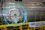
ACBM
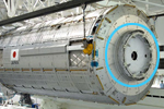
PCBM
(Image credit: NASA)
The PM has an Active Common Berthing Mechanism (ACBM) on the zenith side of the PM for berthing the Japanese Experiment Logistics Module-Pressurized Section (ELM-PS), and a Passive Common Berthing Mechanism (PCBM) on the starboard side of the PM endcone to connect with the ACBM on the port side of the Harmony module (Node 2).
Internal Design
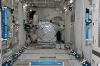
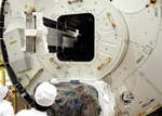
The PM interior after the racks were deployed during the STS-124 Mission (Image credit: NASA)
Currently, the following system racks and International Standard Payload Racks (ISPRs) are in the PM.
- Electrical Power System (EPS) Racks-1 and 2
- Data Management System (DMS) Racks-1 and 2
- Environment Control and Life Support System/Thermal Control System (ECLSS/TCS) Racks-1 and 2
- JEM Remote Manipulator System (JEMRMS) Rack
- Work Station (WS) Rack
- Inter-Orbit Communication System (ICS) Rack
- JEM Resupply Stowage Rack (JRSR)
- SAIBO Rack
- RYUTAI Rack
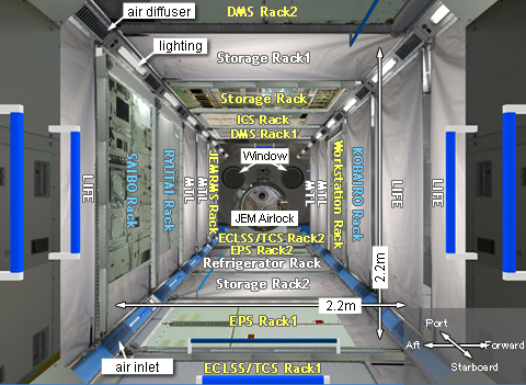
Image of the PM interior. Empty rack booths are covered by dummy panels made of cloth.
LIFE: Life Science Payload Rack
MTL: Material Science Payload Rack
Kibo's system racks
Retrieving or installing a rack
Kibo's core systems which include the Data Management System (DMS), Electrical Power System (EPS), Environment Control System and Life Support System (ECLSS), and the Thermal Control System (TCS), are designed to be operated as two string systems (A-string and B-string) to ensure redundant Kibo operations.
When Kibo is in normal-mode operations, two strings (A-string and B-string) are running simultaneously per system. For example, if one string of the EPS loses power due to some anomaly, the EPS can continue to operate with the other string in a degraded mode.
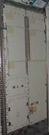
Electrical Power System (EPS) Rack
The Electrical Power System (EPS) Rack consists of the Power Distribution Box (PDB) and the Power Distribution Unit (PDU). The EPS Rack receives electric power (DC120V x 2 strings) generated from the ISS Solar Array Wing (SAW) through Harmony (Node 2) and distributes the received power to Kibo facilities, racks, and equipment aboard Kibo.
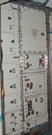
Data Management System (DMS) Rack
The Data Management System (DMS) Rack houses the JEM Control Processor (JCP) and payload data handling unit.
The JCP is Kibo's main computer. Two JCPs operate and control Kibo; one is installed in DMS Rack-1, and the other, in DMS Rack-2.
Environment Control and Life Support System / Thermal Control System (ECLSS/TCS) Rack
The Environment Control and Life Support System / Thermal Control System (ECLSS/TCS) Rack distributes air and coolant water provided from the ISS to each Kibo element.
The ECLSS/TCS controls temperature and humidity inside Kibo's pressurized volume and circulates and freshens the air.
JEMRMS Rack
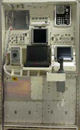
The JEMRMS Console is installed in the JEM Remote Manipulator System (JEMRMS) Rack. A crew member manipulates the JEMRMS with the images taken with TV cameras on the arm, on the TV monitor of the JEMRMS Console.
Work Station (WS) Rack

The Work Station (WS) Rack houses TV monitors, an audio unit, a Caution and Warning panel, and an image switching device.
Inter-Orbit Communication System (ICS) Rack
The Inter-orbit Communication System (ICS) is Japan's unique system for uplink and downlink data, images, and voice data between Kibo and the Mission Control Room at the Tsukuba Space Center (TKSC).
The ICS Rack houses the ICS Pressurized Module (ICS-PM) subsystem that enables data communications between Kibo and TKSC through the Japanese Data Relay Test Satellite (DRTS), known as Kodama. In addition, the ICS Rack includes the Proximity Communication System (PROX) that will be used for the H-II Transfer Vehicle's (HTV) rendezvous and berthing.
Current Status
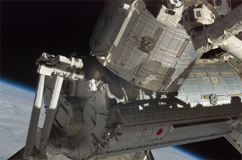
The PM, installed on the ISS during the STS-124 Mission (bottom) (Image credit: NASA)
The PM was launched aboard the space shuttle Discovery and installed on the ISS during the STS-124 Mission.
| Copyright 2007 Japan Aerospace Exploration Agency | Site Policy |