This is an archive of information released in the past.
Disclaimer: It may contain broken links or outdated information. Some parts may not function in current web browsers.
*Visit https://humans-in-space.jaxa.jp/en/ for the latest information.

About Kibo
Japanese Experiment Module Remote Manipulator System
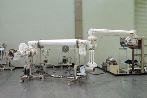
The JEMRMS Main Arm during a sub-system test
Overview
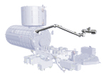
Kibo's robotic arm, Japanese Experiment Module Remote Manipulator System (JEMRMS), is a robotic manipulator system intended for supporting experiments to be conducted on Kibo's Exposed Facility (EF) or for supporting Kibo's maintenance tasks.
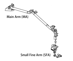
The JEMRMS is composed of two arms, the Main Arm (MA) and the Small Fine Arm (SFA).
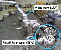
JEMRMS
Both the Main Arm (MA) and Small Fine Arm (SFA) have six joints, thus a great amount of freedom is ensured and human-like movements are realized. The robotic control workstation, known as the JEMRMS Console, is used for manipulating the JEMRMS. TV cameras are mounted on the arms, so the crew members can manipulate the JEMRMS while watching the camera's image on the TV monitor on the JEMRMS Console inside the Pressurized Module (PM).
With these arms, the crew can exchange the EF payloads or Orbital Replacement Unit (ORU) on the EF and Experiment Logistics Module-Exposed Section (ELM-ES). The ten-meter-long Main Arm handles (grapples and moves) EF payloads and large objects, and the two-meter-long Small Fine Arm handles the smaller items.
The JEMRMS will be operated for more than ten years on orbit. Thus, the JEMRMS has exchangeable or repairable design in case of failure. These arms can be repaired by intra-vehicular or extravehicular activities. (The Main Arm can be repaired only by extravehicular activity.)
| Item | Specification | |
|---|---|---|
| Main Arm (MA) | Small Fine Arm (SFA) | |
| Structure type | Main Arm with attached Small Fine Arm. Both arms have 6 joints. | |
| Degrees of freedom | 6 | 6 |
| Length | 10m | 2.2m |
| Mass (weight) | 780kg | 190kg |
| Handling Capacity | Max. 7,000kg (Payload size: 1.85m x 1.0m x 0.8m / weight: less than 500kg) |
Max. 80kg with Compliance Control Mode Max. 300kg without Compliance Control Mode (ORU size: 0.62 x 0.42 x 0.41m / weight: 80kg max) |
| Positioning accuracy | Translation 50(+/-)mm | Translation 10(+/-)mm |
| Rotation 1(+/-)deg. | Rotation 1(+/-)deg. | |
| Translation / rotation speed | 60mm/s (P/L: 600 to 3,000kg) | 50mm/s (P/L: less than 80kg) |
| 30mm/s (P/L: less than 3,000kg) | 25mm/s (P/L: 80 to 300kg) | |
| 20mm/s (P/L: 3,000 to 7,000kg) | - | |
| Maximum tip force | More than 30N | More than 30N |
| Lifetime | More than 10 years | |
Structure
Main Arm
The Main Arm (MA) consists of booms, joints, television cameras (TV Cameras), the camera pan tilt unit (PTU), a light, and the end effector (grapple fixture) that grapples EF payloads. There are three booms, MA Boom 1, 2 and 3. Vision equipment (TV Cameras, PTU and light) is attached to MA Boom 2 and MA Boom 3. The crew manipulates the JEMRMS while watching the images taken with the visual equipment on the TV monitor located on the JEMRMS Console (JEMRMS Rack).
The Main Arm is primarily used for exchanging EF payloads.
Small Fine Arm
The Small Fine Arm (SFA) consists of some electronics, booms, joints, end effectors called “Tools,” and TV cameras. The Small Fine Arm will be attached to the end of the Main Arm when operated.
The SFA handles small items, which includes exchanging the Orbital Replacement Units (ORU) on the EF.
JEMRMS Console (JEMRMS Rack)
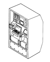
The JEMRMS Console (JEMRMS Rack) is installed in the PM. A crew member manipulates the JEMRMS while watching the images taken with TV cameras on the arm, on the TV monitor of the JEMRMS Console. The JEMRMS Console is composed of a Management Data Processor (MDP), Laptop Computer, Hand Controllers, TV Monitors and Hold/Release Electronics (HREL). The Laptop Computer and Hand Controllers (RHC and THC) are used to manipulate the JEMRMS. The TV monitor displays images acquired by the external cameras.
Current Status
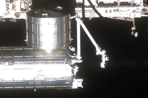
Kibo and JEMRMS, installed on the ISS during the STS-124 Mission (Image credit: NASA)
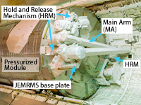
Launch configuration of the JEMRMS
Along with the PM, the JEMRMS was launched aboard the space shuttle Discovery in June, 2008, on the STS-124 Mission (1J).
The JEMRMS underwent various checkouts and test operations in 2008. Currently, in addition to moving and installing exposed payloads, is is utilized for deploying Cubesats into orbit.
| Copyright 2007 Japan Aerospace Exploration Agency | Site Policy |
