| Hyper Velocity Impact Test of Kibo's Debris Shield |
|
A Hyper Velocity Impact Test was conducted
for the debris shield of the Japanese Experiment Module Kibo's Pressurized Module
from July 21 to September 29, 1999. Kibo is designed so that the probability of
its wall not being penetrated due to impacts of space debris or meteoroids during
its ten-year operation period (no-penetration probability) is more than 97 %.
To confirm whether Kibo's wall was manufactured as designed, a series of tests
were conducted to simulate debris impacting with high speed on the debris shield
of Kibo's pressurized module wall.
 | Space
Debris and Meteoroid |
Space debris consists of objects currently circling the Earth after being
launched and completing their duties. It includes used satellites, final
stages of rockets and their components, as well as fragments created by
collisions between those components.
Since the orbital velocity of Space debris is so high, even 1
cm fragments has the energy of a speeding car. In July 1996, a small satellite,
CERISE, collided with a suitcase-size piece of debris and a part of the body was
lost. These days there is a movement to consider this situation as a new space
environment problem.
A meteoroid is a natural object floating in space. When
it comes into the atmosphere it is called a shooting star, and if it reaches the
ground it is called a meteorite.
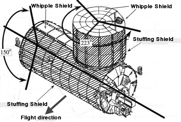
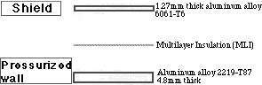
| Kibo's
Debris Shield | The International Space Station (ISS) wall is designed to protect the
ISS and its crew from space debris. A debris shield is adopted for this particular
purpose.
A famous astronomer, Fred Whipple, devised this shield, so it
is called a Whipple Shield. The idea is to attach a layer of thin aluminum plate
outside the wall. When a space debris impacts this outer plate, the kinetic energy
of the space debris is converted to heat. This heat creates a hole in the outer
plate. However, the debris will evaporate or disintegrates to small particles
consisting of gas, liquid and solids and will no longer be able to significantly
damage the wall.
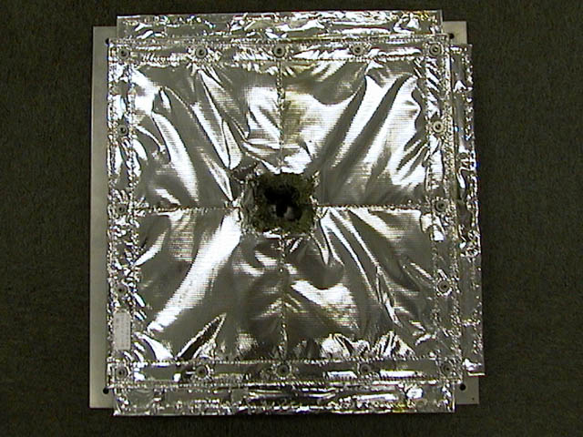
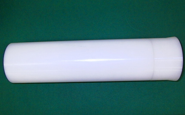
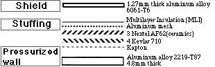
As shown in the figure on the right, a stuffed-shield
is adopted on the wall of the front side of Kibo, covering an area of 150 degrees.
A stuffed shield binds several kinds of textile layers similar to a bulletproof
vest between itself and the wall. This is a reinforced Whipple shield.
|
Whipple shield |  |
| Structure
 |
| Stuffing
shield | |
| Structure
 |
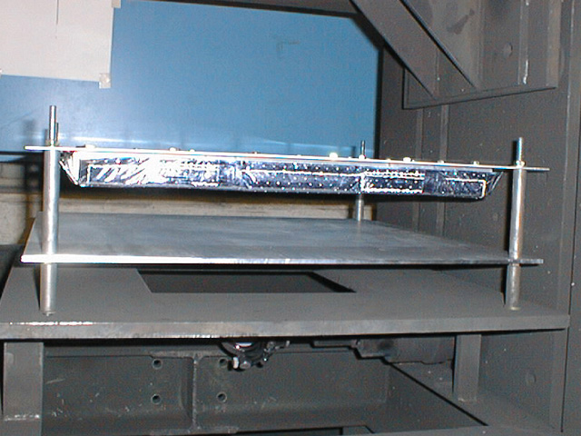
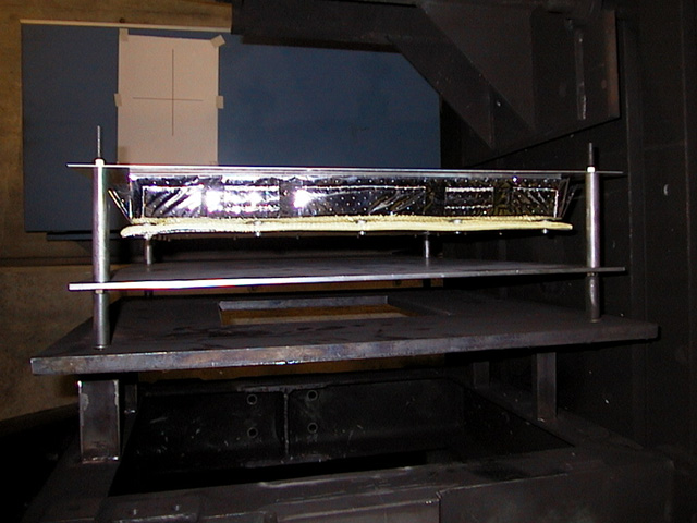
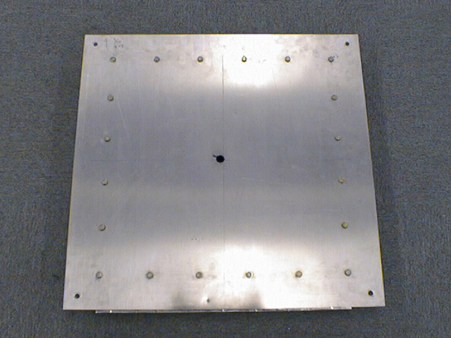
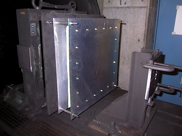
| Hyper
Velocity Impact Test |
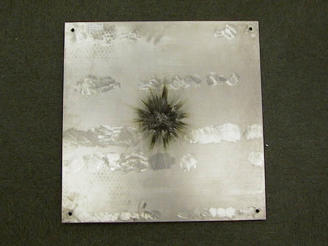
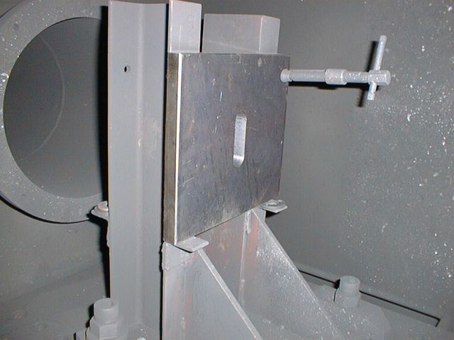
| Test results of simulated
space debris with diameter 11 mm that impacts at a velocity of 5.71 km. |
| | |
| | Shield |
Stuffing | Pressurized wall |
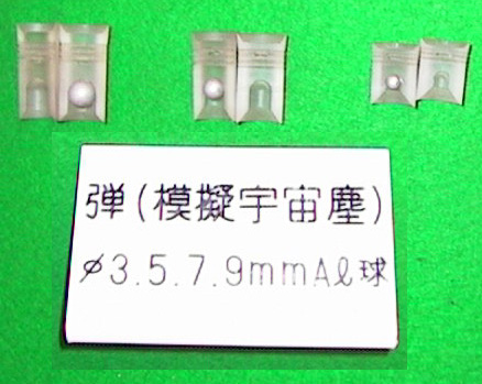
During the series of tests, simulated space debris, aluminum spheres,
with diameters of 5 mm, 7 mm, 9 mm, and 11 mm impacted the wall of Kibo at velocities
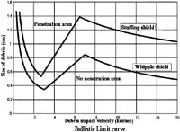
of 2.5 to 6.0 km. In order to evaluate whether the ballistic limit
curve is appropriate, we conducted the tests with a variety of combinations
of debris diameters and velocities. The test results proved that the ballistic
limit curve is appropriate, and Kibo' wall has the strength required.
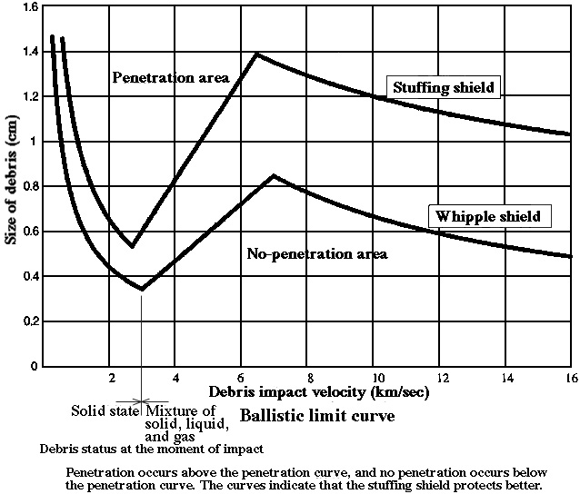
A ballistic limit curve is a graph generated by theoretically
computing the relation between size and velocity of the space debris which penetrates
the wall. This test confirms that the ballistic limit curve
is appropriate, not only theoretically but also practically, and that Kibo has
the required strength as well. However, the projectile velocity generated by the
test equipment is limited. Whether or not projectile will penetrate the wall at
velocities beyond the capability of the test equipment, will be extrapolated from
the ballistic limit curve.
 |
| Ballistic limit curve |
The following space debris policy will be adopted for total
ISS. For space debris with a diameter exceeding 10 cm, compute its orbit before
hand and maneuver the ISS orbit to avoid a collision. If space debris with a diameter
more than 1 cm but less than 10 cm penetrates the wall, astronauts will escape
to an adjoining module and close the hatch. The hole will be repaired later by
EVA. The debris shield will be used to prevent space debris with a diameter of
less than 1 cm from penetrating the wall. Debris penetration will depend on the
velocity and impact angle. As a result, a piece of debris exceeding 10 mm in diameter
might not penetrate the wall, whereas a smaller piece might. International partners
are now cooperating to improve observation ability from the ground so that debris
smaller than 10 cm in diameter can be acquired.
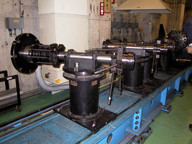
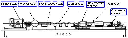
| Test
tool Two-stage light gas-gun | A 21 m-long two-stage light
gas gun facility was developed to fire a projectile into a test object. This facility
was developed to generate projectile velocities of several kilometers per second,
which is much faster than a pistol bullet.
|  | Two-stage
light gas-gun composition | |
| | | Sabot
and Simulated piece of space debris |  |
| Diaphragm |
 |
| Piston |
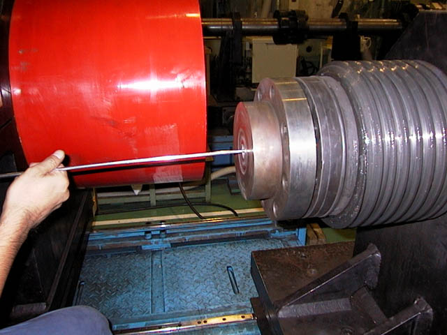
A simulated piece of space debris (aluminum balls with diameter of 3 thru
11 mm (approximately 0.04 thru 1.9 g)), is fired after being inserted into a plastic
case called a "sabot". The aluminum ball can be accelerated efficiently by a highly
pressurized gas. The top of the sabot is hollow, which facilitates its destruction
by air resistance so the aluminum ball inside can escape.
When the gunpowder
is ignited and the exploded gas pressure reaches a predetermined level, the diaphragm,
a thin metal plate, located between the gunpowder chamber and the pump tube is
broken, and the plastic piston is pushed out. The pump tube is filled with a light
gas such as helium or hydrogen and pressurized to seven atmospheres. (note)
The piston pressurizes the light gas inside the pump tube. The pressure of the
light gas breaks the diaphragm located between the high-pressure coupling and
the launch tube. High-pressure gas then bursts into the launch tube and accelerates
the sabot. The piston is stopped by the taper of the high-pressure coupling. The
launch tube and the sample room are filled with 0.1 thru 0.2 atmosphere of nitrogen
gas. The sabot containing the simulated space debris is broken and separated by
the resistance of the nitrogen gas, and stopped by the iron plate sabot trap.
The aluminum ball then leaves the sabot, proceeds straight forward, and impacts
the sample.
The velocity measuring device, located just in front of the sabot
trap, has two coils. The projectile velocity can be measured by measuring the
voltage generated when the sabot with an embedded permanent magnet passes through
the coil.
(note) Highly pressurized gas disturbs the movement of objects
inside. Light gas like helium or hydrogen inside, allows easier movement of the
simulated space debris. |
 |
*Click
parts' names to view their images |
| | Test
Procedure | | | Test
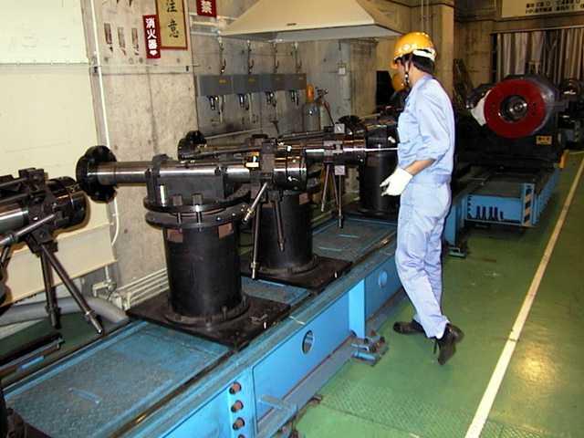
preparation and the test are conducted as shown below. |
Since the above preparations take three to four hours,
a maximum of only two tests is possible per day.
| Interviews
with key persons | | | NASDA
personnel's comments | |  |
During the early test period, we could not start the test because
we had difficulty measuring the speed of the simulated debris. When I finally
resolved the problem in cooperation with experts, I felt quite relieved. The debris
velocity is a very important factor in this test, so we were very concerned about
velocity measurement. In the latter part of the test period, we eagerly sought
to obtain effective data. Based upon the test results of the day, we were anxious
to find the best conditions for the tests of the next day. |
| Kaoru Miyake
JEM project team
Office of Space Utilization Systems NASDA |
| | Interviewing
Mitsubishi Heavy Industry personnel |
|
| |
| | | Mr.
Hiroaki Takahashi | Mr.
Katsuyuki Enomoto | Mr.
Tomikazu Kusumoto | We interviewed Mitsubishi Heavy
Industry's Mr. Takahashi, Mr. Enomoto, and Mr. Kusumoto who were responsible for
conducting the tests.
pjWhat are the most difficult points of this test?
`jThe test itself doesn't take time. However, preparation takes a long time, so
we can conduct tests only twice a day, at most.
pjFor what do you pay
most attention?
`jWe have to be most careful in keeping the firing pipe perfectly
straight. If the firing pipe is not straight, the projectile doesn't fly under
perfect conditions. When assembling the five parts of the firing pipe, we need
to be very careful. The junctions of the pipe have eight bolts, and if even only
one of them is not fastened appropriately, the firing pipe can't be kept straight.
Recovering from such a situation is a messy task. |
Last Updated : September 18,2003
|