|
||||||
Kazunori Kawasaki1, Kazuo Ohta1, Kazunori Matsuo1, and Shinichi Yoda2
1 IHI Aerospace Co., Ltd, 900 Fujiki, Tomioka-shi, Gunma, 370-2398, Japan
2 National Space Development Agency of Japan, 2-1-1 Sengen, Tsukuba-shi, Ibaraki, 305-8505, Japan
As a continuation of the studies performed in the previous fiscal year, the study of feasibility of conducting the dynamic surface deformation measurement on the liquid bridge, to be utilized for the Liquid Bridge Marangoni Convection Experiments using the JEM Fluid Physics Experiment Facility (FPEF), was performed. From these studies, the specifications of the Experiment Cell was established based on the studies of installing the Dynamic Surface Deformation (DSD) Measurement Device into the Experiment Cell, and the detailed measurement based on the Microscopic Imaging Displacement Meter (MIDM) Method for liquid bridge dynamic surface measurement. This study also included the compatibility with the FPEF and confirmed that all interfaces conform to the requirements. Furthermore, items that require confirmation in order to meet the experiment requirements were extracted and a draft of the development plan that reflect these confirmation items was established.
Currently, experiment cells with diameters f30mm and f50mm are being developed for FPEF. In this experiment, the following observations and/or measurements are being planned using the devices equipped in the FPEF Core Section and the Experiment Cell:
The Experiment Cell being planned for this particular research was studied based on the on-going Experiment Cell, with a replacement of Surface Velocity Measurement Device to the DSD Measurement Device, and with considerations of achieving other observations and measurements simultaneously. In addition to the f30mm and f50mm liquid bridge diameters, the study of Experiment Cell specifications for f5mm and f10mm diameters were conducted in response to the plans of experiments using smaller diameters. Moreover, due to the requirement of high resolution for DSD measurement, study was conducted under assumption that DSD image are obtained by CCD Camera using MIDM Method. Finally, the focal points and development plan required to achieve the experiment requirements were proposed.
In establishing the specification of the Experiment Cell, the study was conducted from requirements not only for DSD measurement but also for all other observation and measurements. Table 2-1 shows the requirements for the Liquid Bridge Marangoni Convection experiments, which were used as presumptions for the study.
Table 2-1 Measurement Requirements
| Liquid Bridge Diameter [mm] | 5 | 10 | 30 | 50 |
| Liquid Bridge Length [mm] | 2.5 | 5 | 15,30,60 | 25 |
| 3D-PTV | Not Required | Not Required | Required | Required |
| Onset of Oscillations | Required | Required | Required | Required |
| Surface Temp. | If possible | If possible | Required | Required |
| Dynamic Surface Deformation | Required (0.2 mm) |
Required (0.3 mm) |
Required (0.6 mm) |
Required (0.8 mm) |
| Fluid Temp. | Required | Required | Required | Required |
| Disk Temp. | Required | Required | Required | Required |
| Ambient Gas Temp. | Required | Required | Required | Required |
| G-jitter | Required | Required | Required | Required |
The overall configuration tree of the Experiment Cell is shown in Figure 2-1. The Experiment Cell consists of the Structure, DSD Measurement Device, and the Liquid Bridge Formation Equipment. Four liquid bridge diameters (f5mm, f10mm, f30mm, and f50mm) are being employed, in turn modifications of DSD Measurement Device and Liquid Bridge Formation Equipment are necessitated to meet requirements for each size. For this reason, four types of Optical System and Liquid Bridge Formation Equipment will be developed and each shall be configured to be replaceable on orbit.
Figure 2-1 Configuration tree of Experiment Cell
The following paragraphs list the characteristics of the Experiment Cell for different liquid bridge diameters. Furthermore, the G-jitter measurement was excluded from this study since JEM System Project is planning to install an accelerometer into the FPEF Core Section.
These study results are summarized in Table 2-2.
Table 2-2 Observation/Measurement Summary
| Measuring Item | Liquid Bridge Diameter [mm] | |||
| 5 | 10 | 30 | 50 | |
| 3D-PTV | X | X | O | O |
| Onset of Oscillations | O Back-illumination method Installation of : Exclus. CCD Camera Light Source |
O Back-illumination method Installation of : Exclus. CCD Camera Light Source |
O 3D-PTV (FPEF Core) |
O 3D-PTV (FPEF Core) |
| Surface Temp. | O IR Camera (FPEF Core) Installation of : Macro lens |
O IR Camera (FPEF Core) Installation of : Macro lens |
O IR Camera (FPEF Core) |
O IR Camera (FPEF Core) |
| Dynamic Surface Deformation | O New Development Installation of : Light source |
O New Development Installation of : Light source |
O New Development Installation of : Light source |
O New Development Installation of : Light source |
| Overall Observation | O Exclus. CCD Camera for Onset Oscillation |
O Exclus. CCD Camera for Onset Oscillation |
O CCD Camera (FPEF Core) |
O CCD Camera (FPEF Core) |
| Heating Disk Temp. | 2 Points | 3 Points | 3 Points | 3 Points |
| Cooling Disk Temp. | 1 Point | 1 Point | 1 Point | 1 Point |
| Fluid Temp. | 1 point | 1 Point | 2 Points | 2 Points |
| Ambient Gas Temp. | 3 points | 3 points | 2 points | 2 points |
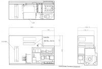
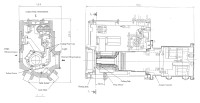
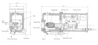
DSD Measurement Device consists of the driving system and the
optical unit. The driving system allows the positioning adjustment in three
axial directions. The mechanism allows adjustment by ground commands for the
liquid bridge's radial and focusing directions, and by crew operation allows
fine adjustment in the liquid bridge's axial direction. In order to measure
curvatures on the edge of the liquid bridge (the boundary between liquid and
atmosphere), Tele-centric optical unit will be utilized. The structure of the
optical unit shall be designed to enable on-orbit replacement for four
different liquid bridge diameters.
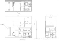
Table 2-3 lists the design specification of the optical unit.
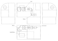
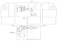
A summarized drawing of the optical path and system is shown in
Figure 2-4.
Table 2-3 Specification of the Optical Unit
| Liquid Bridge Diameter [mm] | 5 | 10 | 30 | 50 |
| Resolution [mm/pixel] | 0.2 | 0.3 (or 0.2) | 0.6 | 0.8 (or 0.6) |
| Field of View [mm] | 128 x 96 | 192 x 144 (or 128 x 96) |
384 x 288 | 512 x 384 (or 384 x 288) |
| Work Distance [mm] | 80 | 80 | 120 | 120 |
The study included the confirmation of the compatibility of the Experiment Cell with the FPEF Core Section on mechanical, electrical, fluid, and optical interfaces.
The conformity of the above interfaces is tabulated in Table 2-4.
Table 2-4 Compatibility with FPEF
| Interface Items | Resource | Liquid Bridge Diameter [mm] | |||||
| 5 | 10 | 30 | 50 | ||||
| Electrical I/F | Electrical Power | +12V | 1 ch | 1ch | 0 | ||
| +24V | 1 ch | 1 ch | |||||
| ±15V | 3 ch | 3 ch | |||||
| Power Amp | 24V -- 1 ch | 1 ch | |||||
| 48V -- 3 ch | 3 ch | ||||||
| Communications | Analog Input | 8 ch | 4 ch | 6 ch | 8 ch | ||
| Digital Input | 8 ch | 4 ch | |||||
| Digital Output | 8 ch | 0 | |||||
| RS422 | 1 ch | 0 | |||||
| Limit Channel I/F | 15 ch | 9 ch | |||||
| Temperature Measurement | Thermocouple (K-Type) |
6 ch | 6 ch | ||||
| Pt Sensor | 5 ch | 5 ch | |||||
| Solenoid Valve I/F | 1 ch | 0 | |||||
| Motor Drive I/F | 4 ch | 4 ch | |||||
| Video I/F (CCD Camera Controller) | 1 ch | 1 ch | |||||
| Video I/F (NTSC I/F) | 2 ch | 1 ch | 0 | ||||
| Fluid I/F | Cooling Water | 1 line | 1 line | ||||
| Gas Supply (Ar Gas) | 1 line | 1 line | |||||
| Gas Vent | 1 line | 1 line | |||||
| Observation Equipment | 3-D Flow Field | 1 | 0 | 1 | |||
| Surface Temperature | 1 | 1 | |||||
| Overall Observation | 1 | 0 | 1 | ||||
| Light (Fiber Head) | 2 | 1 | 2 | ||||
Since silicone oil will be used in this Experiment Cell, several safety topics, especially regarding flammability and toxicity shall be concerned.
Silicone oil has been identified as a flammable substance. To control against flammability, a double sealing similar to the one applied in the current Experiment Cell design will be provided and an Argon-gas replacement in the Liquid Bridge Formation Equipment will be performed.
The toxicity level of the silicone oil is evaluated primarily based on its amount and appropriate countermeasures (such as redundant sealing) corresponding to the toxicity level is required. The amount of silicone oil currently being planned would unlikely require any control.
Small-diameter (f5mm and f10mm) liquid bridge experiment in microgravity environment has not been conducted in the past so this liquid bridge formation technique would be a new developmental element.
For f30mm and f50mm diameter liquid bridge, an o-ring is placed in the cooling disk to prevent leakage of the sample (silicone oil) and ingression of air bubbles before forming the liquid bridge. For small diameter liquid bridge, o-ring cannot be placed in the cooling disk therefore testing of small-diameter liquid bridge formation including the prevention of air bubble ingression into the sample is necessary.
The development flow of the new Experiment Cell is shown in Figure 3-1. Upon proposing the development plan, the following development approach will be employed:
Figure 3-1 Development Test Flow
In this study, the specifications of the Experiment Cell were established and the interfaces with the FPEF Core Section were confirmed to be compatible.
Furthermore, as stated in Section 3, the feasibility of forming
small-diameter liquid bridge, which has never been conducted, need immediate
investigation.