|
|||||
SPECIFICATIONS Protein Crystallization Research Facility (PCRF) Solution Crystallization Observation Facility (SCOF) The main purpose of using SCOF is to observe the crystallization process of many kinds of solutions. The observation includes interferometry, direct observation, photon-detection-counting and other methods and devices that support the accomplishment of many experiments. The experiment is performed using an automated program, which processes the experiment according to experiment parameters set in advance and installed in the program. In addition, tele-science operations are possible during the automated experiment by sending commands or parameter files to change or correct the experiment's performance. SCOF features the following main components:
The Main Section, which includes all components except the Experiment Cell Cartridge (Experiment Cell Section), consists of the following observation devices: Mach-Zehnder Microscopic Interferometer Michelson Microscopic Interferometer
Amplitude Modulation Microscope, Polarized Light
Microscope, Bright-Field Microscope
The Experiment Cell Section is developed and prepared
by each researcher based on the experiment requirements. In addition, each
Experiment Cell Section can use these observation devices by utilizing
the resources provided by SCOF Main Section Observation Systems The following diagram shows the observation mechanism of SCOF.
SCOF Observation System (A) Mach-Zehnder Microscopic Interferometer
The Mach-Zehnder Microscopic Interferometer can be used to observe
the crystal growth using two different wavelengths that can be used to
measure and analyze the temperature and concentration distribution of the
solution in liquid-phase. The light path for the Mach-Zehnder Microscopic
Interferometer follows the "vertical" axis so that passes through
the Experiment Cell Cartridge from "top" to "bottom."
Dynamic Light Scattering Measuring Device (DLS) Fluorescent Decay Measuring Device Reflection Spectrum Equipment (RSE)
Other Devices In order to utilize the capability of Dynamic Light Scattering Measuring Device, the Experiment Cell Section needs to prepare a Photon Detector and optical fiber while Photon Counter and Hard Correlator Boards are already installed in the Main Section. The particle size distribution can be measured using a Hard-Correlator Method. The DLS has the following specifications:
This device shares the light source with DLS and a Photon-counter
card is installed in the Electronic Controller (E-CONT) in the Main Section.
The Experiment Cell Section needs to prepare a Band-path Filter that meets
the electrical and mechanical interfaces supported by the Main Section.
If the researcher requires Reflection Spectrum Equipment (RSE) for
the experiment, SCOF Main Section provides physical
and electrical interfaces for the Reflection Spectrum
Equipment (RSE), including a RS232C Communication interface. The RSE itself
needs to be developed by the Experiment Cell Section based on the interface
and experiment requirements.
If the researcher requires to use an Absorption Photometer, SCOF
Main Section providesphysical and electrical
mechanical, and optical interfaces
to utilize the Absorption Photometer. Like RSE, the Absorption Photometer
itself, including a halogen lamp and optical fiber, needs to be prepared
by the Experiment Cell Section.
(5) Other Devices (E)Image data store and downlink capability Real-time image data can be stored in digital videotapes in IPU, and can be real-time downlinked through IPU in real time. In addition, the following components in the Main Section support the observation of the crystal growth:
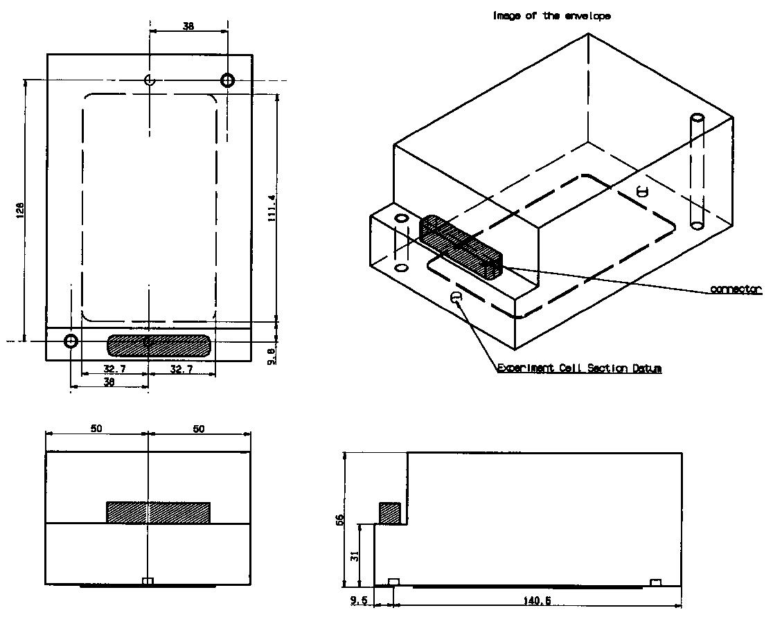
These interfaces are controlled by the Interface Control Document (ICD) in which the English version will be available by middle of Year 2001. A brief description of these interfaces is shown in the following paragraphs. For details of these specifications, please refer to the ICD. The principal envelope allowed for the Experiment Cell is 65 mm x 220 mm. However, an additional envelope of 300 mm x 120 mm x 240 mm may be utilized if any of the additional devices is required for the experiment.
The mechanical mounting interface called Cell Stage is located on
the Cell Driving System just inside of the door on the Operation Panel.
Two pins and a mark are available to align the Experiment Cell and the
Cell Stage. The Experiment Cell shall be fastened with screws attached
to the Cell Stage. An additional mechanical interface is available
to attach the additional devices prepared by the researcher onto SCOF.
This additional interface is located at the top rear of the Operation Panel.
Unlike Cell Stage, only some holes are provided on a bracket such that
the additional device may be attached using screws.
SCOF Main Section provides power and signal lines to the Experiment
Cell Section through six (6) connectors. The interface includes signals
and power to thermistors, thermo-modules, heaters, thermocouples, pressure
sensors, motors, and limit switches. In addition, data transmission through
RS232C is available when using the RSE or other
optional device. The following table shows the summary of these functions.
For details, please refer to the ICD.
The electronic controller regulates all of these interfacing lines
according to the experiment parameters preset into the software. Examples
of the parameters include the timing to control the temperature to a target
value, the selection of laser type, and selection of the observation device
at different timing. Some of these parameters may be changed during the
experiment by tele-science operation.
(D) Thermal Interface
(E) Optical Interface
The Cell Driving System consists of motors that can be used to drive the Cell Stage (approximately }3.0 mm translation in three directions and }10 degrees rotation along the vertical (Z) axis) for optical adjustment of the Experiment Cell; mostly focusing and positioning.
(F)
Fluid Interface
Back
to top The main purpose of using PCRF is to generate high quality and large protein crystals by controlling the temperature of the specimen. Four crystallization methods are being employed on PCRF and all four methods can be processed simultaneously. Like SCOF, experiments on PCRF are performed using an automated program, which processes the experiment according to experiment parameters set in advance and installed in the program. Similarly, tele-science operations are possible during the automated experiment by sending commands or parameter files to change or correct the experiment's performance.
PCRF
features the following main components:
Unlike SCOF, PCRF has only one observation system that consists of the following components: CCD Camera Optical Lens Assembly Camera Movement Mechanism
PCRF Observation System
Image
data store and downlink capability
Interface Requirements between the Main Section and the Experiment Cell Section Like SCOF, the interface requirements with the PCRF Main Section need to be met in order to develop the Experiment Cell Section for each experiment. The Main Section provides the following types of interfaces: No fluid interface is provided for PCRF. However, like SCOF, these interfaces are controlled by the Interface Control Document (ICD) in which the English version will be available by middle of Year 2001(TBD). A brief description of these interfaces is given below:
(A)
Physical Envelope
(B)
Mechanical Interface
(C)
Electrical Interface
Like SCOF, the electronic controller in PCRF Main Section regulates all
interfacing lines according to the experiment parameters preset into the
software. Examples of the parameters for PCRF include the timing to control
the temperature to a target value, the duration of observation on one specimen,
and the X-Y coordinates of the Cell (specimen) with respect to the camera
for camera movement observation. Some of these parameters may be changed
during the experiment by tele-science operation.
(D)
Thermal Interface
The
observation system in PCRF is has the following specifications:
The camera can observe only one cell at a time but the camera can be moved
to different positions at any time using commands or crew operations. (See
the drawing)
Last update: November 21, 2003
|