 |
| SRTM coverage |
SRTM (Shuttle Radar Topography Mission) is mounted on a Space Shuttle and
obtains Earth surface data by remote sensing technology utilizing a synthetic
aperture radar. Obtained data will be converted into height data called
a Digital Elevation Model (DEM), and will be utilized to generate a more
precise three-dimensional map of larger observation area of the Earth than
has ever been possible.
During its 11-day flight, it will obtain data covering 80% of the Earth's
surface (excluding north and south poles), and 95% of its residential area.
The high-resolution,digital,three-dimensional topographic map produced
from this data will be disclosed to the general public in the hope that
it will be used in various fields. Potential applications include regional
weather forecasting that takes account of topography,obtaining an accurate
understanding of the distribution of forests in mountains, safe navigation
of aircraft,and determining line-of-sight areas in wireless communications.
- The third Space Radar Experiment
SRTM is a Space Radar Lab (SRL) experiment payload promoted by NASA.
Following the flights of STS-59 (SRL-1) and STS-68 (SRL-2) launched in
1994, STS-99 will be the third flight (SRL-3). Since SRL-3 uses an outboard
antenna mounted at the end of the 60m extended mast, which was not used
in SRL-1 and 2, it will obtain higher quality data, which will be utilized
to generate three-dimensional images of the Earth.
- International Project
SRTM is an international mission in which the organizations below participate;
- NASA JPL
Performs SIR-C system development, operation, and total project management.
- German Aerospace Center (DLR)
Performs X-SAR development, operation, and management.
- Italian Space Agency (ASI)
In cooperation with DLR, ASI participates in X-SAR development, operation,
and management.
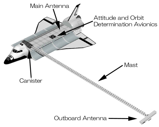
- Characteristics of SRTM
In order to generate a three-dimensional map, it is necessary to collect
data from two viewpoints. As shown in the illustration, two antennas, the
main antenna mounted in the cargo bay of the Shuttle and another one mounted
at the end of the 60m extended mast on the port side of the cargo bay,
will be used. The observation data of these two viewpoints and a technique
called interferometry will be used to generate three-dimensional images
such as shown below. This is one of the features of SRTM.
Another feature is the ability to extend the mast up to 60m on orbit. This
mast was developed based on the mast that will be used to deploy solar
panels of the International Space Station(ISS). However, the mast for SRTM
is twice as long. This mast will be the longest structure ever deployed
in space.
While data is being collected, the antenna mounted at the end of the 60m
mast must be properly positioned within several millimeters, which requires
highly advanced techniques. Also, as many photographs as possible will
be taken by the camera during this flight. These photographs will then
be compared with radar images.
 |
 |
| Antenna being
deployed |
NASA/JPL/Caltec |
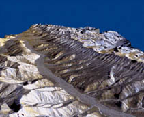
Sample of three-dimensional image
by STS-59 and 68 |
As shown below, SRTM is composed of the main and outboard antennas of SIR-C/X-SAR
which uses two frequency bands, Attitude & Orbit Determination Avionics
(AODA; electronic equipment used to determine attitude and orbit), a mast
that extends 60m from the shuttle, and a canister to store the mast, and
a structure to support all the equipment.
 |
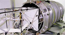
| NASA/JPL/Caltec |
| Main Antenna |
|
|
 |
| NASA/JPL/Caltec |
| Outboard Antenna |
|
|
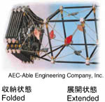
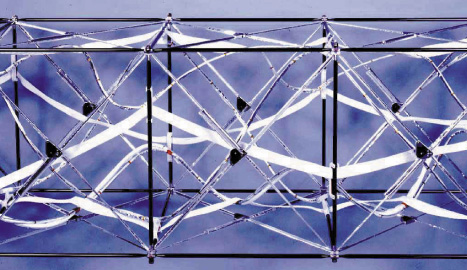
Model of mast |
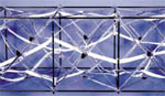 |
| AEC-Able Engineering Compay, inc. |
| Exterior of Mast (three bays) |
|
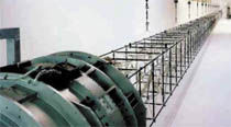 |
| AEC-Able Engineering Compay, inc. |
| Mast in fully extended state |
|
|
- Main antenna
This is a 12 m-long,4 m-wide transmitting and receiving SIR-C/X-SAR antenna.It
is mounted on the support
structure in the shuttle cargo bay.
- Outboard antenna
This is a receiving-only SIR-C/X-SAR antenna and is mounted 60 m from the
port side of the shuttle.
During the launch, the outboard antenna is stored in the cargo bay of the
Shuttle; it will be deployed at the end of the 60m mast before observation
starts.
- Attitude &Orbit Determination Avionics (AODA)
In order to perform data processing for creating a high-resolution,three-dimensional
topographic map,it is necessary to obtain extremely accurate information
concerning errors in the position and attitude of the antenna during measurement.
This information is measured using the AODA system,which consists of highly
accurate sensors including a GPS receiver, equipment for measuring the
distance between the main antenna and the outboard antenna,and an optical
sensor that uses a light emitting diode.These devices are controlled and
monitored by the crew in the shuttle,using an AODA processing computer
(APC).
- Mast
This mast extends 60 m from the port side of the shuttle and supports the
300 kg outboard antenna at its end.
During launch and return to Earth,the mast is folded to about 1/20th of
the fully extended length.The mast
comprises some 87 cubic bays,each of which consists of support columns
made of high-strength compound material, metal wires,joints,and so on.
This mast was developed by the US AEC-Able Engineering Company Inc.,utilizing
the technology that it developed for the mast deploying the solar array
wings used in the International Space Station.
Such a long mast has never been used in space. Whether SRTM program will
be successful or not will strictly depend on extending and retracting this
mast.
-
 |
| AEC-Able Engineering Compay, inc. |
| Canister |
Canister
The canister houses the mast during launch and return to Earth.It is 1.4
m in diameter and 2.9 m long.The mast is
extended and retracted by a motor installed inside the canister.
- Payload High Rate Recorder (PHRR)and Recorder Interface Controller
(RIC)
The shuttle has six PHRRs,and two RICs that control the PHRRs on board.Three
PHRRs record data during
observation,and remaining three are in reserve.RIC is a laptop computer:One
RIC is always used to control the
PHRRs,and the other is spare.
It will take one year to one year and half after the shuttle returns to
Earth to process the extremely large amount of data (9.8 terabytes;one
CD contains 650 megabytes,so this amount is equivalent to 15,000 CDs)that
will be acquired.
Major specification of SIR-C/X-SAR
| item |
SIR-C
Spaceborne Imaging Radar-C |
X-SAR
X-band Synthetic Aperture Radar |
| Size |
Main antenna |
12.0m X 3.5m |
12.0m X 0.5m |
| Outboard antenna |
8.1m X 0.9m |
6m X 0.4m |
| Frequency |
5.3GHz |
9.6GHz |
| Wavelength |
5.8cm |
3.1cm |
| Resolution |
Horizontal |
30m |
30m |
| Vertical |
16m |
16m |
| Altitude |
233km |
233km |
| Swath width |
225km *2 |
50km |
| Polarization *1 |
HH,HV,VH,VV |
VV |
| Off nadir |
23 - 63 degree *2 |
52 degree |
| *1 |
F |
HH (Horizontal transmit,Horizontal receive)
HV (Horizontal transmit,Vertical receive)
VH (Vertical transmit,Horizontal receive)
VV (Vertical transmit,Vertical receive) |
| *2 |
F |
SIR-C is designed with Scan SAR.The beam can be electronically steered. |
|
| Last Updated : September 1, 1999 |
|