
| Detailed Description of SRTM Observation Principles
(2) |
|
Attitude of shuttle
 The
attitude of the shuttle used in this mission is very distinctive. The
attitude of the shuttle used in this mission is very distinctive.
The main antenna in the shuttle cargo bay is installed obliquely on the
support structure in the cargo bay so that the antenna face is tilted at
an angle of 14 degrees with respect to the horizontal surface of the cargo
bay.The outboard antenna is oriented to the north,and the shuttle flies
tilted at an angle of 59 degrees with respect to the line perpendicular
to the surface of the Earth.This is to maintain the orientation of the
antenna and the angle of the mast at 45 degrees with respect to the line
perpendicular to the surface of the Earth.This attitude increases the coverage
of the Northern Hemisphere,which contains large areas of land.
The shuttle flies with the tail section facing the direction of travel,and
the cargo bay facing the direction of the Earth to reduce the risk of space
debris colliding with the windows of the shuttle.
 |
Scan SAR observation image acquired using the shuttle
Scan SAR is a technology in which the antenna beam is scanned in order
to increase the coverage.There are two methods of scanning the beam,one
in which each of the phases transmitted from multiple phase detectors mounted
on the antenna is changed so as to scan the beam electronically,and one
in which the antenna itself is moved so as to scan the beam mechanically.
In SRTM,SIR-C is using Scan SAR and the beam is
scanned electronically.
*: On SRTM, the shuttle flies with the tail section facing the direction
of travel. |
Technical Difficulties Attendant to SRTM
- Deployment and retraction of the mast
The mast is 60 m long.This is the longest articulated structure to be used
in space up to now.During launch and return to Earth,the mast is folded
to about 1/20th of the fully extended length,and stored in a canister in
the cargo bay.The technology for deploying and retracting the mast while
twisting it in the reverse direction one bay at a time by means of the
motor in the canister was a technical challenge for the mission.The mast
starts to be extended about 5 hours and 30 minutes after lift-off,and takes
17
minutes to fully extend.
If the mast cannot be extended or retracted due to a breakdown of the equipment,this
work will be done manually from outside the shuttle (EVA).
- Minimizing changes in attitude due to external disturbances or vibration
On this mission,the shuttle will travel at a speed of about 7.7 km per
second with the mast extended.The main antenna and outboard antenna will
be subjected to external disturbances due to the effect of gravity *1
,and to vibration due to shaking and flexing of the mast as a result of
the daily orbit control (thruster jet)of the shuttle.The alignment between
the main antenna and the outboard antenna must be within +-0.03 degrees,so
highly accurate control isrequired.
Attitude control and maneuver,which greatly change the attitude of the
shuttle,are performed above the sea when observations are not performed.Control
is made for the influence in attitude due to the effect of gravity,by slowly
and continuously releasing jets of nitrogen gas from thrusters installed
at the end of the outboard antenna while observation is taking place.Misalignment
of the outboard antenna during observation is corrected by the crew at
appropriate intervals.
*1: A spacecraft that has a long axis and travels in a low orbit
(orbit altitude of no more than 1,000 km)tends to assumed an attitude and
gravity gradient such that one end faces the Earth and the other end faces
the opposite direction.
History of the Synthetic Aperture Radar for Use in Space
SAR was conceived immediately after the appearance of radar technology
at the beginning of the Second World War. Subsequently,the US actively
researched SAR from both the theoretical and empirical aspects.As a result,by
the latter half of the 1950s,six kinds of experimental aircraft SAR systems
had already appeared.
Observations from space using SAR started from the US oceanographic observation
satellite SEASAT in 1978.SAR observations were subsequently carried out
using Japan Earth Resources Satellite-1 (JERS-1),the European Space Agency's
(ESA)ERS-1 and ERS-2,and Canada's RADARSAT.
SAR missions using the shuttle started from STS-2 in 1981.The first SAR
employed was the Spaceborne Imaging Radar (SIR)-A.Subsequently,an improved
version of SIR-A was used in STS-41G (SIR-B),and a further improved version
called SIR-C was used in STS-59 and STS-68.From STS-59, a X-SAR synthetic
aperture radar that operates in the X-band was installed together with
SIR-C,hence the name of the Space Radar Laboratory (SRL)was used for the
name of the shuttle mission.
Year and month
of launch |
Mission name |
Country where mission
was developed |
Features |
| December 1972 |
Apollo 17 |
US |
The moon's surface was measured using the first space SAR in history.
This SAR was called Apollo Lunar Sounder Experiment (ALSE). |
| June 1978 |
SEASAT |
US |
The first artificial satellite to carry SAR.Was designed to conduct
oceanographic observation. |
| November 1981 |
STS|2/SIR|A |
US |
Shuttle-mounted SAR. |
| November 1983 |
STS|9/MRSE |
Germany |
One of the experiments in the Spacelab mission. |
| October 1984 |
STS|41G/SIR|B |
US |
Shuttle-mounted SAR.Improved version of SIR-A. |
| May 1989 |
Magellan |
US |
Venus probe.First SAR designed for planetary exploration.Three-dimensional
map of the surface of Venus was produced. |
| March 1991 |
ALMAZ|1 |
USSR |
SAR installed. |
| July 1991 |
ERS|1
*1 |
ESA |
C-band SAR installed. |
| February 1992 |
JERS|1
*2 |
Japan |
L-band SAR installed. |
| April 1994 |
STS|59/SRL|1 |
US |
Shuttle-mounted SAR.Improved version of SIR-B and X-SAR installed. |
| October 1994 |
STS|68/SRL|2 |
US |
Shuttle-mounted SAR. |
| April 1995 |
ERS|2
*1 |
ESA |
C-band SAR installed. |
| November 1995 |
RADARSAT |
Canada |
C-band SAR installed. |
| October 1997 |
Cassini |
US |
Saturn probe.Ku-band SAR installed.To be used to observe the surface
of Titan,a satellite of Saturn. |
*1FEuropean Remote Sensing Satellite-1,2 @*2FJapan
Earth Resources Satellite-1
Utilization of Three-Dimensional Maps
The high-resolution,three-dimensional topographic map obtained as a result
of this mission can conceivably be used in the following three ways.
- A topographic map that was previously expressed by drawing contour
lines on a paper map can be treated as a digital elevation model.Consequently,it
is possible to combine satellite image data with various geographical information
and data,such as maps and statistical information,and create a geographic
information system on a computer.Conceivable applications of such a system
include resource management in agriculture and forestry,understanding the
environment,mineral resource
development,conservation of the regional living environment on a local
government scale,town planning
and development,and surveying a disaster situation over a wide region.
- Earth observation data that was previously obtained in two-dimensional
form can now be obtained as data that includes differences in topography.This
data can be used for regional weather forecasting that takes account of
topography,improving climate models,obtaining an accurate understanding
the distribution of forests in mountains,and so on.
- A three-dimensional map can be used in applications that use a bird's-eye
view to express the geographical relationship between points more clearly
than a plane map. Examples include town planning,creation of road traffic
networks,architecture that takes account of the overall landscape,car navigation
systems,and determining line-of-sight areas in wireless communications.
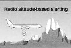 |
| GPWS |
A more practical example for improving aircraft safety is described here.
Since the 1970's, aircraft have been equipped with a ground proximity warning
system (GPWS) to prevent sudden crashes into mountains or the ground. When
a radio altimeter detects that an aircraft is approaching the ground, the
GPWS initiates aural or visual warnings. However GPWS is not effective
for steep slopes where sometimes crashes can't be avoided. Most aircraft
accidents with casualties are caused by aircraft crashing into the ground
before the crew becomes aware of the danger.
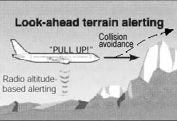
During the past several years, airlines have been installing an Enhanced
GPWS (EGPWS). This system has global geographical data, and data of obstacles
close to airports all over the world. This system is able to warn the crew
of potential crashes into slopes or mountains, which considerably increases
safety. Unfortunately the Earth map data utilized for this purpose has
an accuracy of only 500m to 1000m. Data obtained by the SRTM mission could
be applied to EGPWS to produce a system with higher precision.
 |
|
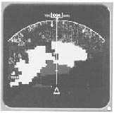 |
| Enhanced GPWS (EGPWS) |
|
EGPWS Display |
Courtesy of ANA
| Last Updated : September 1, 1999 |
|