Summary of Space Shuttle robot arm (Shuttle Remote Manipulator System:
SRMS)
 |
Use of Shuttle Robot Arm |
The Shuttle's robot arm is used for various purposes.
- Satellite deployment and retrieval
- Construction of International Space Station
- Transport an EVA crew member at the end of the arm and provide a scaffold
to him or her. (An EVA crew member moves inside the cargo bay in cooperation
with the support crew inside the Shuttle.)
- Survey the outside of the Space Shuttle with a TV camera attached to
the elbow or the wrist of the robot arm.
|
Dimensions |
|
Length
|
45 feet |
|
Diameter
|
15 in |
|
Weight
|
911 lb |
|
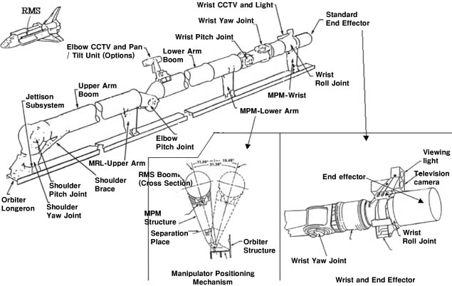
Number of joints
|
Six joints (two shoulder joints, one
elbow joint, and three wrist joints) |
|
Max handling capacity
|
266 tons (in space) |
|
Max velocity of end of arm
|
When the arm is not gripping anything
: 60 cm/sec
When the arm is gripping an object : 6 cm/sec |
|
Max rotational speed
|
Approx. 5 degree/sec |
|
Boom material
|
Graphite-epoxy compound |
|
|
|
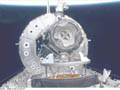
Shuttle robot arm (SRMS) observed from the aft deck.
|
|
|
| Overview shape of SRMS |
|
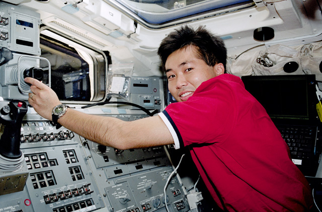
SRMS operation |

Robot arm operation (STS-92) |
SRMS is operated inside the Space Shuttle cabin. The operation is performed
from the aft flight deck (AFD), right behind the cockpit, either through
the window or by watching two TV monitors.
To control the SRMS, the operator uses the translational hand controller
(THC) with his or her left hand and manipulates the rotational hand controller
(RHC) with his or her right hand.
Translational hand controller (THC) |

Rotational hand controller (RHC) |
|
How Space Shuttle robot arm grasps objects. |
|
|
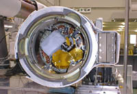
End effector of Kibo's manipulator. Same shape as SRMS.
|
How does the Space Shuttle robot arm grasp objects? Many people might think
of human hand or magic hand, but its mechanism is as follows.
At the end of the robot arm is a cylinder called the end effector. Inside
this cylinder equiped three wires that are used to grasp objects. The object
to be grasped needs to have a stick-shaped projection called a grapple
fixture. The three wires in the cylinder fix this grapple fixture at the
center of the cylinder.
However, a sight is needed to acquire the grapple fixture while manipulating
a robot arm as long as 45 feet. The grapple fixture has a target mark,
and a rod is mounted vertically on this mark. The robot arm operator monitors
the TV image of the mark and the rod, and operates the robot arm to approach
the target while keeping the rod standing upright to the robot arm. If
the angular balance between the rod and the robot arm is lost, that can
immediately be detected through the TV image.
Grapple fixture/Target |
End effector and grapple fixture |
-
|
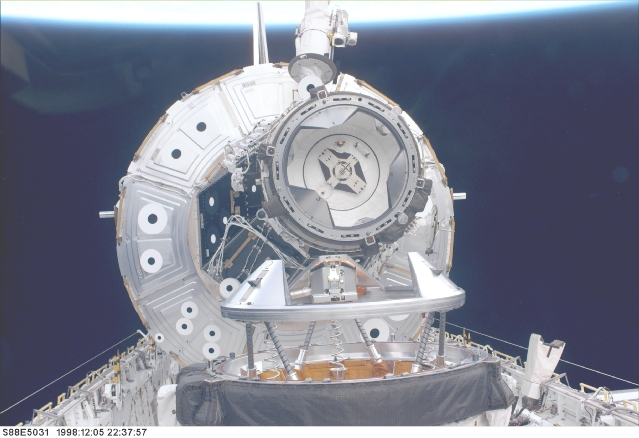
SVS(Space Vision System) |
 |
SVS target attached to the Unity module (black round
spots with white backgr
ound) |
The Space Vision System (SVS) is an aid developed by Canada and the US
to precisely measure the location, attitude, and moving rate of objects
in real time by analyzing the TV image of the SVS target.
Several dot patterns on a payload or ISS elements are used as SVS targets.
Three- dimensional fine positions of these targets are measured on the
Earth prior to flight, and the data are referenced for measuring the movement
of the target. Optical characteristics of the TV camera lenses need to
be acquired beforehand as well. SVS information will be displayed on the
monitor graphically and numerically for use of astronauts.
For measurement, at least three SVS targets must be visible and five targets
are preferable. Since distortion due to lighting or thermal conditions
could cause errors, these effects must be minimized.
During Shuttle robot arm (SRMS) or the International Space Station (ISS)
robot arm (SSRMS) operations to assemble the ISS, SVS will be a necessary
technology used in combination with TV camera images when the operator
can't directly(note) see the objects to be manipulateed.
Note. Before the ISS assembly began, Shuttle robot arm operations were
performed by a crew member watching the manipulated objects through the
Shuttle window.
|
Robot arm operation mode |
The robot arm can be operated by Space Shuttle crew members. However, automatic
mode, in which the robot arm moves automatically along a trajectory computed
on the Earth is also possible. There is also another mode in which single
joint can be driven. These methods are selected to suite the needs of the
operation.
|
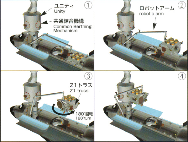
Procedure for installing the Z1 truss using the robotic arm |
 |
|
Procedure for installing the Z1 truss using the robotic
arm
|
First, using the Shuttle's robotic arm, grapple the Z1 truss which is anchored
to the cargo bay. Next, operate to release the latches which are holding
the Z1 truss in the cargo bay, then unberth the Z1 truss.
Manipulate the robotic arm while observing the camera image on the TV monitor
installed on the operation console, then slowly maneuver the Z1 truss toward
Unity.
Turn the Z1 truss 180 degrees in order to bring the side to be connected
into line with Unity.
After bringing the Z1 truss to a point about 60 cm from Unity, use the
Space Vision System (SVS) to continue to move the Z1 truss accurately toward
the connecting point with Unity. Using the capture latch, temporarily connect
the Z1 truss to the Common Berthing Mechanism (CBM) of Unity, then send
an instruction from the Shuttle to install the Z1 truss to Unity using
the 16 drive bolts inside the CBM. This will be the first attempt to conduct
connecting of ISS modules in space by using a CBM.
|
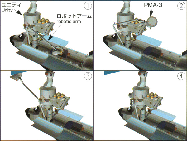
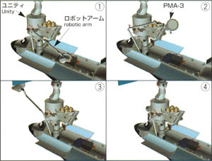
PMA-3 installation procedure using the robotic arm |
 |
|
Procedure for installing the Z1 truss using the robotic
arm
|
The procedure for installing PMA-3 is basically the same as that for the
Z1 truss. At first the EVA crew members will release the bolts that fasten
the PMA-3 to the cargo bay.
Then Astronaut Wakata will unberth the PMA-3 from the cargo bay and maneuver
it to Unity by using the robotic arm. The same way as the Z1 truss, PMA-3
will be installed to Unity by using the position and attitude information
of the Space Vision System, while the EVA crew members will observe the
operations.
|