This is an archive of information released in the past.
Disclaimer: It may contain broken links or outdated information. Some parts may not function in current web browsers.
*Visit https://humans-in-space.jaxa.jp/en/ for the latest information.

Experiment
- News
- Kibo Utilization Strategy
- Kibo Utilization Plan
- List of JAXA's Utilization Themes
- Experiment Facilities
- Space Environment Utilization
- Archive
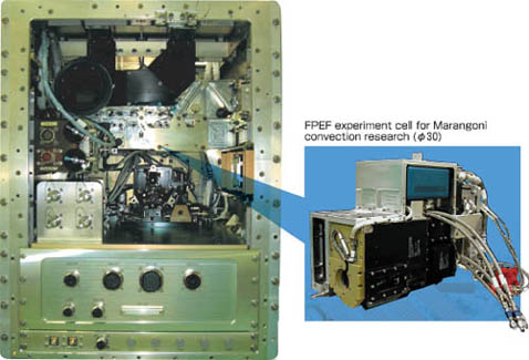
Fluid Physics Experiment Facility (FPEF)
A MULTI-USER EXPERIMENT FACILITY TO INVESTIGATE FLUID PHYSICS PHENOMENA IN A MICRO-GRAVITY ENVIRONMENT
Overview
Experiment facility to investigate fluid physics phenomena in a micro-gravity environment
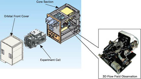
The FPEF consists of the core section and the mission section. The core section has observing equipment, the control equipment, and miscellaneous experiment support systems.
The mission section called as the "Experiment Cell", is exchangeable according to the purpose of the experiment.
The FPEF's observation capabilities include liquid bridge overview observation, three- dimensional flow field observations, surface- temperature measurement, ultrasonic velocity profile measurement, and surface-flow rate observation.
Resources for experiments
Various resources provided to users

The FPEF provides users' experiment cells with electrical resources through electrical connectors and fluid resources through Quick Disconnect (QD)s. [Electrical Resources] ·Power ·Signal ·Video etc. [Fluid Resources] ·Ar gas ·Water coolant
Users can conduct a variety of fluid experiments utilizing these resources.
Experiment cell
Development of the Experiment Cell for Marangoni convection research
The Experiment Cell is exchangeable according to the experiment purpose.
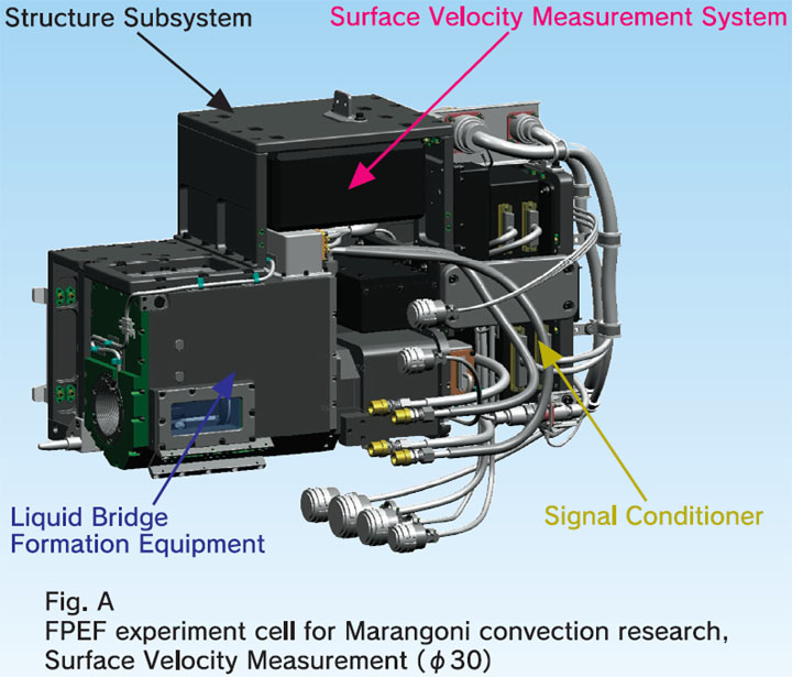
Fig. A
FPEF experiment cell for Marangoni convection research, Surface Velocity Measurement (φ30)
The experiment cell consists of liquid bridge formation equipment, heating disk, cooling disk, sample cassette, surface-flow velocity measurement assembly, and structure subsystem.
It is also permitted to users to design and fabricate their own mission section determined by themselves, providing that it satisfies the core/mission section interface
Experiment operation
Flexible experiment operations and provided experiment image data
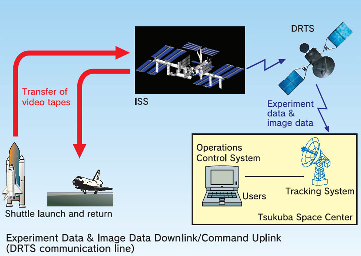
Experiment Data & Image Data Downlink/Command Uplink
(DRTS communication line)
Users can monitor both the status of experiment data measured by each sensor and the experiment image data via a satellite circuit in real time.
The experiment image data are downlinked to the ground for real-time monitor, and at the same time, recorded on the built-in digital Video Tape Recorder (VTR) for later analysis.
Specifications
| Item | Specifications | ||||||||||||||||||||||||||||||||||
| Liquid Bridge Formation |
|
||||||||||||||||||||||||||||||||||
| Temperature Monitor |
|
||||||||||||||||||||||||||||||||||
| Temperature Control |
|
||||||||||||||||||||||||||||||||||
| 3D Flow Field Observation |
|
||||||||||||||||||||||||||||||||||
| Liquid Bridge Overview Observation |
|
||||||||||||||||||||||||||||||||||
| Surface Temperature Measurement |
|
||||||||||||||||||||||||||||||||||
| Surface Flow Velocity Measurement |
|
||||||||||||||||||||||||||||||||||
| Ultrasonic Velocity Profile Monitor |
|
||||||||||||||||||||||||||||||||||
| User Interfaces |
|
||||||||||||||||||||||||||||||||||
| Copyright 2007 Japan Aerospace Exploration Agency | Site Policy |